The fixed installations of the CFDs

The fixed installations of the CFDs

Facilities that are easy to adapt

The Company had created a type of facility that could be easily adapted to the needs of the traffic by adding additional trackage. It consisted of a main track and a 200-metre-long siding spurred at both ends onto the main track.

Access to our range of locomotives

The layout of the tracks in the stations

This siding was extended by an 80-metre-long dead end with a weighbridge and loading gauge. There were two wharves, one between the two tracks for a length of 60 metres, the other along the B.V. for a length of 40 metres.

Medium-sized stations had an additional 220-metre-long siding and a third 60-metre platform.

Smaller locations were served by stops with a B.V. without a hall and a 60-metre platform along the main track. When traffic demanded, this facility was supplemented by a siding and dead end for carload service (stops open for P.V. service).

The logistics centres were equipped with a special bundle of lanes for the traction department facilities to serve the various workshops and equipment sheds.
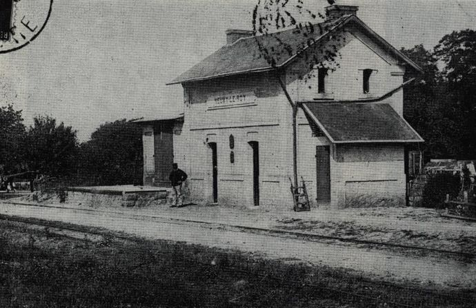
Building type Port-Boulet-Châteaurenault (P.B.C.): Neuvy-le-Roi. (Collection J. RENAUD)

The buildings

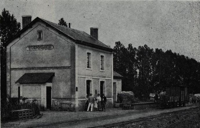
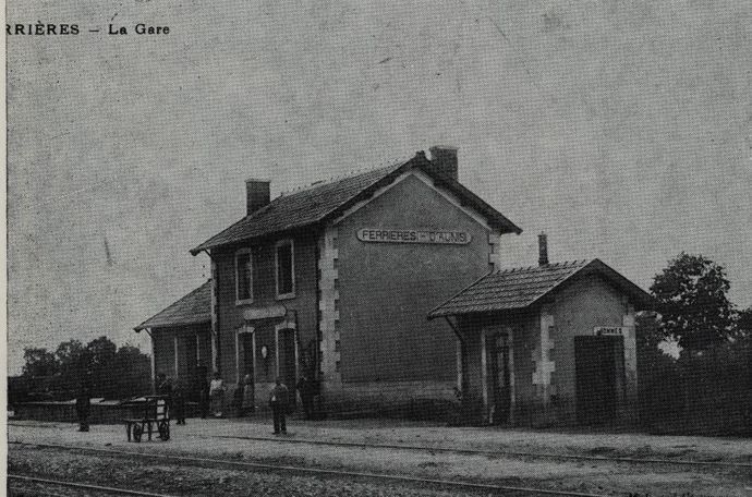
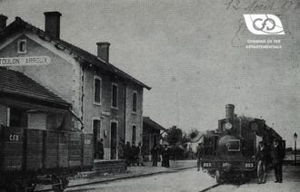
The passenger building (B.V.) had the waiting room and the ticket distribution office on the ground floor. Upstairs were the rooms and living quarters of the station manager. A goods hall and a loading bay were attached to the B.V. A lean-to for the use of a toilet, urinal and lampstand was set up against the gable opposite the hall.

In some important stations, a small special aedicula was built for this purpose. Water was supplied by a well dug near the B.V.

Building type n° 3, 1st series: Genillé (Indre-et-Loire south). (Collection G. PEREVE)

The stops were equipped with a B.V. without a hall.

The buildings on the first line from Port-Boulet to Château-Renault were of an economical type, without a floor, but various disadvantages resulting from their small size prompted the Company to adopt the floor model mentioned above.

In the larger stations, the halls were separated and the stations serving the livestock areas were equipped with a cattle platform.

The different types of buildings

The various types of buildings are briefly described below:

  • Type No. 1 had a central building with three doors and three windows on each side. It was flanked on either side by two wings with two rooms on the ground floor.
  • Type No. 2 had only one-piece wings.
  • Type No. 3 consisted of a two-storey B.V. with two doors and two windows on each side. It was attached to a freight hall.
  • Type No. 4 had only a Type No. 3 B.V. without a hall.
  • Type No. 5 consisted of a guard house with an adjoining room used as a waiting room.
Building type n° 3, 2nd series and W.-C. aedicula : Ferrières-d'Aunis (Charentes). (Collection R. VERGER)

Types 1 and 2 had a separate hall.

As for the stopping points intended to serve hamlets, some of them sometimes had a shelter closed on three sides; the others were signalled only by a simple signpost.

The logistics centres were equipped with machine sheds, workshops and wagon rooms. These sheds were sometimes large and could house up to nine machines. An office-store building and a housing unit for the heads of departments were also built there.

Building type n° 2, Yssingeaux (Vivarais). (Collection J. RENAUD)

A shed for a machine was usually built in terminal stations. It was supplemented by a fire pit, a fuel yard and a swing bridge.

Guard houses were set up for the N.P. service at major roads.

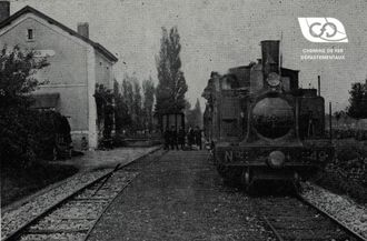
General view of a C.F.D. type station with water tower and rolling gates: Ligny-le-Châtel (Yonne). (Collection J. RENAUD)

Water supply

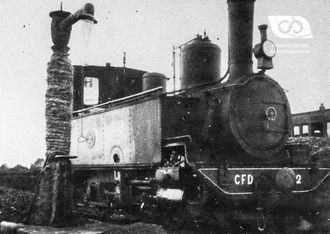
The locomotives were to be supplied with water, on average, every 15 to 20 kilometres. A reservoir located at one end of the siding had a direct connection and a hydraulic crane was located at the other end. At the common stations, the hydraulic cranes were sometimes connected to the reservoirs of the large networks or to the local water pipes.

In areas where the water was overloaded with mineral salts, water purifiers of the Desrumeaux type were installed, to prevent incrustations in the boilers. The reservoirs had a capacity ranging from 12 to 50 m3 depending on the number of machines to be fed. Initially, these cylindrical sheet metal tanks were placed on a cubic base. Later, they were placed on masonry towers.

Shelter building for stops: Ceriseaux (Seine-et-Marne). Mallet 2 locomotive + 2 No. 44. (Collection J. RENAUD)

Level crossings

N.P.s were mostly unguarded. On busy roads, they were provided with a guard house. Originally used rolling barriers were gradually converted into revolving barriers, and towards the end of the operation they were almost all converted into swinging barriers. On smaller tracks near a station, the barriers were placed under the responsibility of the stationmaster.

source : MTVS 1981-3

Related Articles

The CFD Company

in the face of the second world war

After having faced the First World War, the C.F.D. company was at its peak an...

The CFD Company

CFD lines and track

The composition of the C.F.D.'s patrimony.

At the time of the Company's most prosperous period, around 1930, the total l...

CFD lines and track

The operation of CFDs

The creation and supply of a machine in less than a year

CFD Company's experience as an operator, now a hundred years old, and the dyn...

The operation of CFDs
Contact us