Locomotives with radial axle at the rear; type Yonne

Locomotives with radial axle at the rear; type Yonne

After consulting its usual Belgian manufacturers, the Company chose the GT type from the Société de Saint-Léonard in Liège. This model with a rear carrying axle, equipped with radial gearboxes, placed under the driver's cab, differed from that of the S.E. by its Walschaert distribution and its lower power.

Access to our range of locomotives

Description of the Yonne type locomotive

Compared to the Indre-et-Loire 1-8 series, they were equipped with driving wheels of an increased diameter (0.900 m), allowing them to be used without damage at higher speeds. Like the latter, the suspension springs of the driving axles were combined by balancers, but the driving rods attacked the third axle. The smoke box door was always double-leafed and the steam dome, also located on the first shell, carried the balance valves. The sand tank was located on the second ferrule.
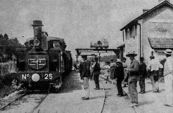
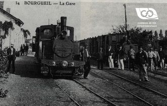
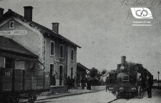
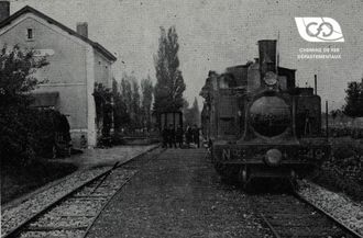
Locomotive 031 Saint-Léonard n°25 in Massangis station, on the Yonne line

The shelter, with a front wall pierced by two visor bays, was open at the sides and at the rear. Four columns supported the roof. A sheet metal sheet was quickly installed at the rear to protect the driving crew. Later, depending on the network, the workshops installed either a leather curtain or a glass frame on the front sides.

A handrail was attached to the water boxes and to the upper part of the smoke box.

Later, as boilers were changed, a round smoke box door was placed on some units.

The decoration was identical to that of the previous series 1-8 with oval plates on the water boxes and marking on the front and rear crossmembers with the words "N °" and the registration on either side of the central stamp.

Later, as the G.R. was passed through, this marking was modified by affixing the Company's acronym on either side of the stamp. However, a few units were marked with the abbreviation on the left and the registration on the right. It seems that these modifications did not occur in Indre-et-Loire.
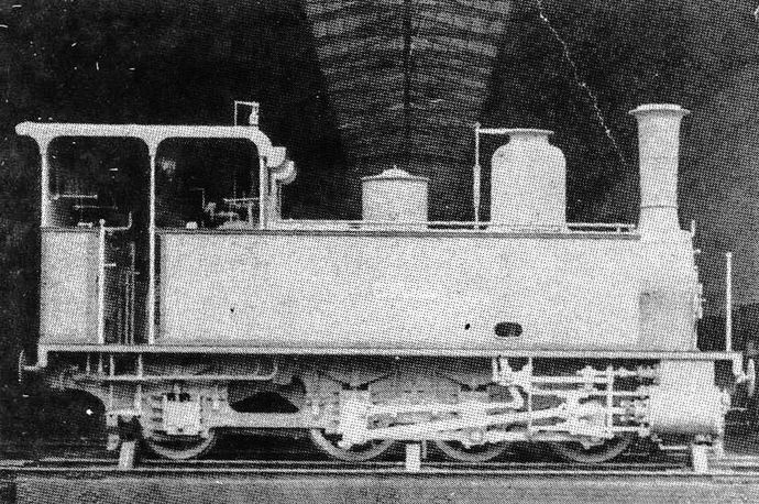
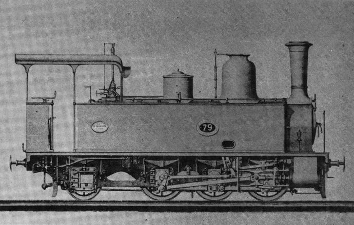
Locomotive GT Saint-Léonard type Yonne in the manufacturer's workshops

Delivery and assignment of the Yonne type locomotive

Dating from 1885, the first order for 12 units to equip the Yonne and Seine-et-Marne networks was also divided between the Saint-Léonard and Marcinelle and Couillet factories. This first series, whose registration of the units making it up had been taken following the work machines 11-12, was to be allocated at the rate of :

  • 6 units for the Yonne
  • 6 units for Seine-et-Marne, including 3 for Montmirail and 3 for Egreville.
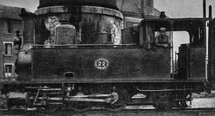
Elevation view of a Yonne type locomotive. Here the n°22 in Laroche-Migennes station

However, because of the urgent need for traction equipment for ballasting and track laying, the Company had the first three Couillet delivered to Chablis (13 to 15) and the fourth to Montmirail (16). The next three, of Saint-Léonard construction, were directed to Egreville (19 to 21) and the rest of the series to Chablis (22 to 24). The last two Couillet were assigned to Montmirail (17 to 18). However, these machines had some differences between them, namely :

  • boiler of 109 tubes of 2.30 m in length with a total heating surface of 35.07 m2 for machines 13 to 16.
  • boiler of 113 tubes of 2.42 m in length with a total heating surface of 39 m2 for machines 17 to 24, and once the work was completed, the C.F.D. decided to group together identical machines on the same lines in order to facilitate maintenance.
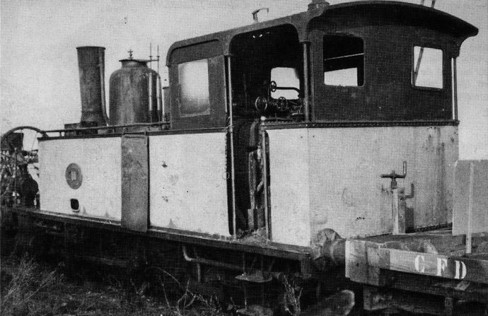
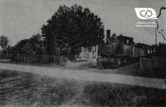
Yonne type locomotive, rear view. Here, n° 14 at the Egreville depot

In the meantime, in 1886, a second order for 7 additional units was placed with the same establishments to equip the lines of the South Indre-et-Loire network, 4 at Couillet and 3 at Saint-Léonard.
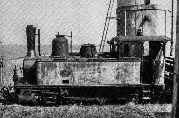
Yonne type locomotive seen in elevation. Here the n° 14 at the Egreville depot

These new units were numbered from 25 to 27 for those coming from Saint-Leonard, following the previous order, and the four others were assigned Nos. 9 to 12, thus filling the corresponding gap in the logical sequence of registration of locomotives intended for the operating service, eliminating from this series the work machines 11-12 assigned to the construction service. We have seen earlier that the latter were assigned to operations as of 1900, which led the Company to consider their re-registration. However, it was decided to suspend their registration as long as the machines remained assigned to different networks, which was also the case for the Lagny type machines and the 4-5 Saint-Léonard series.
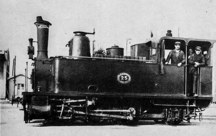
Yonne type locomotive n° 25 during shunting in Laroche-Migennes station

Different boilers

These two sub-series also have different boilers:

  • type 113 tubes of 2.42 m length for machines 9 to 12
  • type 113 tubes, length 2.65 m for machines 25 to 27, for a total heating surface of 42.30 m2

The C.F.D. endeavoured to allocate these new units in order to limit as much as possible the use of different spare parts in the same depot.

As a result, the following changes were made:

  • removal of the 13-16 series from Chablis and Montmirail and assignment to Ligueil for the 13, 15 and 16 and Egreville for the 14. During its general overhaul, the latter received a replacement boiler series 9-12. The dismantled boiler was placed in the Ligueil depot as a replacement.
  • assignment of locomotives 9 and 11 at Montmirail
  • assignment of locomotives 25 and 26 at Chablis.
  • assignment of locomotives 10, 12 and 27 to Ligueil.
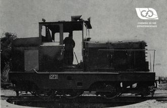
Manufacturer's photo of the Saint-Léonard GT3 locomotive type

This new distribution carried out from 1888 to 1889 made it possible to group together machines 13-16 in Ligueil, identical units of the 19-24 series in Chablis and those of the 9-12 and 17-21 series in Seine-et-Marne.

There was nevertheless, in Ligueil, a rather heterogeneous park where three different types cohabited. This situation was re-established in 1908, by limiting to two types the residents of this depot by exchange with that of Egreville of the machines n° 20 and 27.

In 1900, a complementary order for two new units was placed with the Société de Saint-Léonard, in order to reinforce the fleet of the Seine-et-Marne and Yonne lines. This manufacturer had been chosen because of the harmonization of the models used in these depots, on the one hand, and on the other hand because of the congestion in the workshops of the French manufacturers. Of the GT3 type, these two machines numbered 79 and 80, following the series in progress at that time, had a boiler type 113 tubes and a total heating surface of 39 m2, but the stamp was high from 10 to 12 kg, the wheels had a diameter of 0.910, and therefore the rigid wheelbase increased from 2.15 to 2.45 m and their weight was 1 t higher than that of the previous series.

As soon as they were received, they were assigned to Egreville for the 79 and Chablis for the 80. The latter remained attached to its original depot, however the 79 joined the Mortcerf depot in 1906, to replace the failing 83, then the Meaux depot in 1934, after the closure of the Lagny line.

These machines were very popular and could tow a 40-ton convoy at a speed of 20 km/h on a hilly course with 20°/°° ramps. They were used until the closure of the networks to which they were attached.

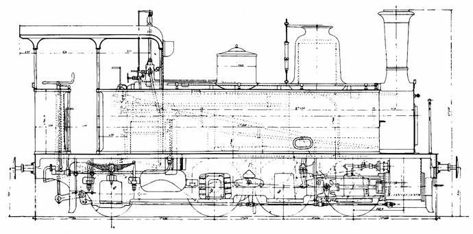
Plan of locomotive type 031 Saint-Léonard. (Scale 1/43.5)
{d}13.10.87{d}13.10.87{d}13.10.87{d}St Leonard{d}13.10.87{d}13.10.87 tractor{d}13.10.87 Tractor Y
DELIVERY TABLE FOR YONNE TYPE LOCOMOTIVES
No. C.F.D. No. Con. BuilderYear of ConstructionDelivery DateCommissioning Date
9840Couillet1887 27.09.0828.01.89Reform 1947
10841d°188727.09.8718.07.88Reform 1947
11842d°188812.06.8828.01.89Reform 1957
12843d°188812.06.8816.05.89Reform 1937
13825d°188617.07.86Reform 1947
14826d°188617.07.86Reform 1956
15827d°188617.07.86Reform 1951
16828d°188617.07.8629.05.88Reform 194 T
17829d°188727.09.8729.05.88Tractor 851
18830d°188727.09.8729.05.88Tractor 852
19722188629.10.8629.05.88Reform 1950
20723d°188626.12.8629.05.88Reform 1950
21724d°188626.12.8529.05.99Reform 1942
22725d°188626.12.86Reform 1952
23726d°188626.12.86 X
24727d°188626.12.86Y
25733d°188617.01.8708.05.88Reform 1952
26734d°188617.01.8705.05.88Reform 1952
27735d°188714.02.8724.08.89Reform 1950
791278d°190124.09.0118.11.01Reform 1956
801279d°190115.01.0120.11.01Reform 1952

The dates indicated in the "Commissioning" column are those of the Prefectorial Order authorizing the circulation to the commercial service. Machines 9 to 27 all operated ballast and track laying trains from the "delivery date" until they were used for operation.

source : MTVS 1988-4

Related Articles

The CFD Company

in the face of the second world war

After having faced the First World War, the C.F.D. company was at its peak an...

The CFD Company

CFD lines and track

The composition of the C.F.D.'s patrimony.

At the time of the Company's most prosperous period, around 1930, the total l...

CFD lines and track

The operation of CFDs

The creation and supply of a machine in less than a year

CFD Company's experience as an operator, now a hundred years old, and the dyn...

The operation of CFDs
Contact us