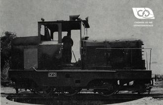
S.N.C.F. BB 71000 locomotives.

S.N.C.F. BB 71000 locomotives.

by Messrs ZENS, Chairman, and HONNORE, Chief Executive Officer of the Compagnie de Chemins de Fer Départementaux.

The MONTMIRAIL Workshops of the Departmental Railway Company, which had long specialised in the construction of metric track DIESEL locomotives, then built normal track DIESEL locomotives for low-traffic lines.The qualities of this equipment and its ease of operation thanks to the ASYNCHRO hydromechanical transmission led the S.N.C.F. to place an order with these 640 HP locomotive workshops which we present in the following lines.

Access to our range of locomotives

General information

The S.N.C.F. has just put into service 30 640 HP locomotives for the operation of its secondary lines and for shunting in its marshalling yards.

The main feature of these machines, is the choice of transmission.

Abandoning conventional solutions, i.e. electric transmission and hydraulic transmission, it has adopted a hydromechanical transmission " ASYNCHRO ".

For several years, the S.N.C.F. had been interested in this new type of transmission and had followed the tests of a 600 HP prototype made by the Ateliers de Montmirail.

This prototype in particularly hard service, having proved to be interesting for its price, performance and adhesion, the S.N.C.F. commissioned the company FIVES LILLE to build a series of 30 machines of the same design.

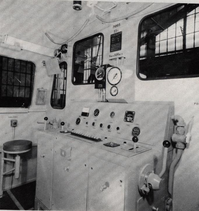
Driver's console
Driver's console

The main features of the BB 71000 locomotive are as follows

The main characteristics of this locomotive are as follows:

  • Type : BB with bogies
  • Total length: 11,900 m.
  • Overall width: 2,800 m.
  • Overall height: 4,030 m.
  • Wheelbase of a bogie: 2, ? m.
  • Total wheelbase: 7,670 m.
  • Bogie centre distance: 5,600 m.
  • Wheel diameter: 0.860 m.
  • Curb weight : 52,50 T.
  • Operating weight: 55,? T.
  • Minimum radius of inscription: 80,? m.
  • Maximum speed: 80,? km/h.
  • Maximum hook effort on starting: 16,700 kg.

Direct and automatic brakes - compressor from 3.000 1 /m. to 1.350 r/m. at 9 bars.

Hydromechanical transmission "ASYNCHRO" 8 speeds.

A technological description

The chassis

It is constituted by 2 I-irons of 500 strongly braced and the head crossbeams form a very robust boxing.

A hood covers the mechanical assembly at the front, i.e. the engine and transmission.

Its end covers the radiators and the compressor.

At the rear, a smaller hood contains the air tanks, the machine's pneumatic control unit, and the lubricant supply.

The driver's cab is raised, soundproofed and mounted on rubber blocks to filter out vibrations from the engine.

It includes a console which serves as a support for the control levers and the control devices. This console allows two driving positions except for the use of the automatic brake.

The bogies

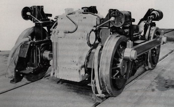
They are type DIAMOND.

They include a cross beam which is connected to the frame by 2 superimposed toads.

Traction and braking forces are transmitted from the bogie frame to this cross member via 2 return rods to Silentbloc.

Each of the bogies comprises a driving axle driven by a triple reduction reversing axle and a driving axle coupled to the other by connecting rods. These axles are mounted with 0.860 m wheels with pneumatic tyres. The ball bearing axle boxes are inside the wheels.

The suspension is made by 4 coil springs on each side.

Two "REPUS- BUCKET" hydraulic shock absorbers on each bogie brake the large amplitude oscillations.

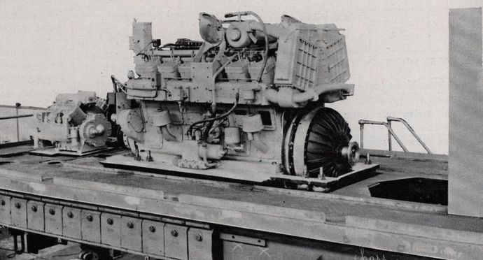
The motor

It is a 12-cylinder type A POWDER rod. 12. 150 Sr high pressure supercharged by 2 Holset 4 ". turbochargers

Its rated power is 640 HP (470 kw).

Its nominal speed is 1,650 rpm.

However, the hydraulic governor H25BPZ2P5U72L of the engine allows, in 8th gear, to give the engine a speed of 1.800 rpm with 85% of load; which corresponds to a speed of 80 km/h. for the locomotive.

The

The transmission includes a hydraulic coupler " FERODO 26 " with cooling fins, fixed on the engine flywheel

This coupling is only used for starting, thus avoiding the use of friction surfaces that would wear out quickly. It allows very soft starts and at high speeds it has an excellent performance

(98 %).

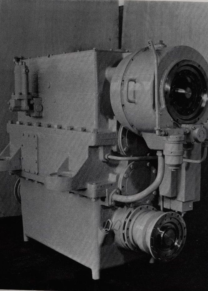
A cardan shaft connects it to the gearbox. This "ASYNCHRO" gearbox includes :

Bogie
Bogie
  • a clutch-brake,
  • a gearbox with 8 combinations,
  • and 2 identical free wheels on either side of the output shaft.

Each output has a PTO shaft. These shafts drive 2 reversing reduction axles mounted on each of the end axles of the bogies.

This gives full grip on all 4 axles.

However, thanks to the freewheels, any possibility of overloading the cardan shafts is eliminated as they cannot work against each other.

Furthermore, in the event of engine damage, the engine cannot be damaged and is protected from backlash by the freewheels.

The first gear is used for hilltop disconnections, 650 rpm motor

  • speed 3 km/h. In this case, the engine governor works as an "all speed" governor.
Poyaud engine
Poyaud engine

A so-called manual 1st gear allows the starting of heavy trains, or in particularly difficult conditions. For the use of the machine in all speeds, except in 1st gear, the engine governor works as a min-max governor.

The 2nd gear is the normal starting speed.

The 3rd gear allows you to make the "throws".

The higher speeds are normal line speeds and give :

  • 3e speed 16.1 km engine at 1,650 rpm.
  • 3e ? 21.8 ?
  • 5e ? 30, ?
  • 6e ? 40.4 ?
  • 7e ? 54.5 ?
  • 8e ? 73.2 ?
  • 8e ? 80, engine at 1,800 rpm.

The operating principle of the "Asynchro" gearbox

The difficulty in transmitting high power in gearboxes does not come from the gears, which have no limit other than that of the peripheral speed of the teeth, but from the difficulty of coupling when changing combinations of pinions with large and different relative speeds because the inertias increase very rapidly with their dimensions.

If, in the low power gearboxes, it has been possible to interpose real brake synchronizers absorbing the difference in the kinetic energies of the pinions to be coupled, it can be seen that their dimensions increase faster than those of the gears. These synchronizers therefore have a limit.

Gearbox Asynchro
Gearbox Asynchro

In the "ASYNCHRO" transmission, to change gears, the gearbox is totally isolated and stopped by placing a clutch-brake at the input and free wheel outputs.

This means that the sprockets can be locked in less than one second when stationary, but the braking torque is no more than a quarter of the engine torque.

The clutch-brake between the engine and the gearbox is a multi-disc clutch-brake operating in oil. The clutch-brake is normally spring-loaded. A pneumatic piston allows the clutch to be released and the gearbox brake discs to be applied at full travel.

The air acting on this piston allowed to disengage and stop the gearbox as well as to control the engine idling. With the gearbox at a standstill, it is very easy to change the combination and thanks to a distribution of compressed air to the pinion control elements, the pre-selected combination is engaged.

This operation is extremely fast, in the order of one second. The clutch-brake cylinder is vented, the brake is released and the clutch is re-engaged. For a given pressure, the engine is put back into gear, its recharging being timed.

The gearbox has 8 combinations and the gears are continuously engaged. Four claws make the series connection of 3 stages of 2 speeds (2 X 2 X 2). The gear ratio of the gearbox is 1.35.

The axles have 3 reduction stages, giving a gear ratio of 1:5.59, the first stage being the bevel gear reverser. The shuttle is pneumatically operated.

The principle of gear control

The control lever placed on the console, can occupy 4 positions:

  • direct locomotive brake,
  • engine idling, transmission disengaged,
  • transmission clutch, engine at idle,
  • engine acceleration.

A speed manipulator gives the following possibilities :

  • work of the locomotive on the hump,
  • manual control of the gearbox,
  • automatic order,
  • engine" overspeed control with 15% load reduction at 8th speed.

The main control available to the locomotive engineer, acts on an air regulator which, via an electro-pneumatic distribution block, controls the engine speed in the "hill-up" position of the speed manipulator, and the engine torque for all other positions of this speed manipulator.

On this machine with automatic or manual gearshift control, the transmission combination shift cycle is fully automatic

In manual control, the judicious choice of the combination to be engaged and the moment when this operation must be carried out is up to the driver, who, by moving the gearshift lever from one stable position to another stable position, will trigger the gearshift in order :

1° an impulse which will start the stage change cycle,

2° a new excitation of the solenoid valves controlling the rods which will correspond to the stage chosen by the mechanic, and will allow the end of the cycle for the passage of the suit.

In automatic control, the gearshift lever must be in the CA2 or CA3 markings. In this case, the choice of the combination to be engaged and the moment when this operation is judicious, is entrusted to an automatic system which prevents the mechanic from having to change the combination.

The choice of the "moment" at which the stage change must be triggered when the stages are raised or lowered is given by the engine, taking into account its instantaneous speed and load. The latter is interrogated by two centrifugal contactors, one of which gives a test at rated speed and the other a test at the lower operating speed of the engine. Finally, a microswitch tests the position of the rack and thus the load of the motor.

In conclusion, for an instantaneous engine speed higher than 1,640 rpm and for a load less than or equal to 74%, the engine will command the stage change to the upper stage, and for an instantaneous engine speed lower than 1,180 rpm, it will command the stage change to the lower stage.

These two tests together constitute the "engine test" or the choice of the "moment".

The choice of the combination to be engaged is given by the speed of the machine. This is the "axle test". A tachometric dynamo constantly gives a voltage proportional to the speed of the machine. This voltage is applied to the terminals of a cabinet with three voltage relays connected in parallel and whose adjustment by fixed resistors, according to their excited or non-excited state, makes it possible to carry out the 8 combinations according to the logical diagram below.
12345678
RELAISA OEOEOEOE
RELAISB OOEEOOEE
RELAISC OO0OEEEE

O -> not excited

E -> excited

These indications are transmitted to the gear control solenoid valves so that a new combination can be selected in the gearbox.

A voluntary delay in the excitation of the relays at the moment when the motor test of stage ascent is to be given, allows the de-energization of these relays in advance of the motor test, of downshift. In order to obtain a correct display of the stage to be engaged at stage rise, the "motor test", which alone has the decision power to trigger the automatic combination changeover cycle, causes an overvoltage in the voltage relay circuit by short-circuiting a resistor.

These two tests "axle" and "motor" are grouped together in a relay box. These relays are necessary to take into account the real traction phenomena, and to obtain optimum stability of the automatic speed control.

It should be noted that this automatic control system uses only 4 power lines, three of which are used to select the combination, the fourth being used to synthesise the two tests and to trigger the stage change impulse.

(APPENDIX TABLE of charges)

Locomotive BB 71 000. Freight Equipment Trailer

Performance tests

As soon as the first machines came out, very extensive tests were carried out on one machine (BB 71 002). These tests highlighted the excellent efficiency of the type of transmission, thus allowing higher than expected performance

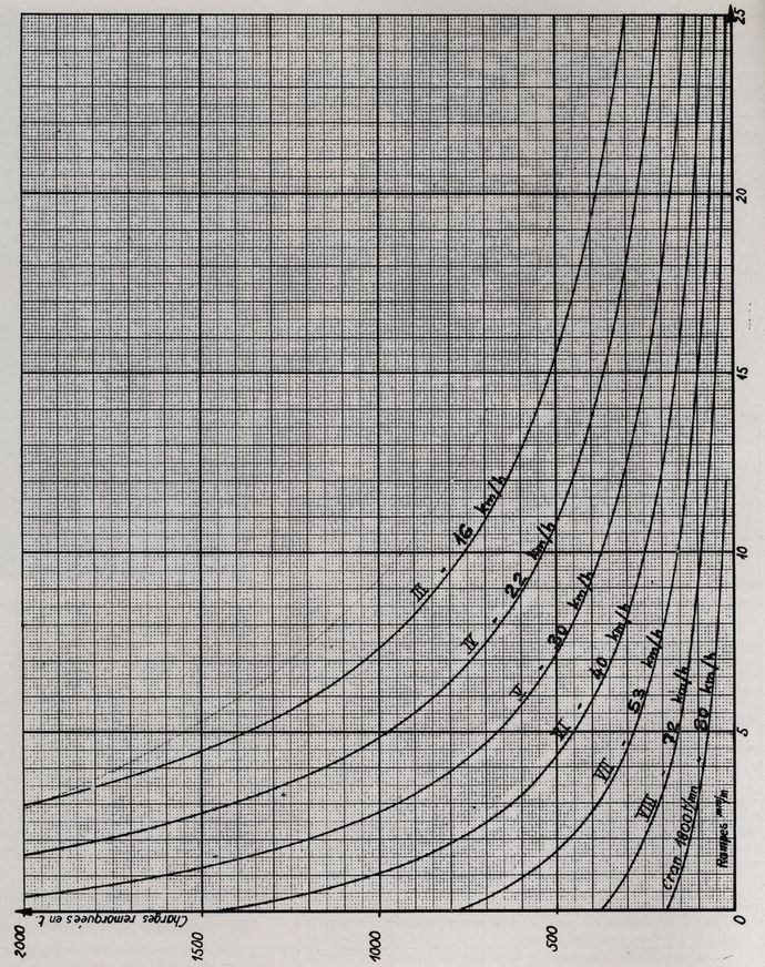
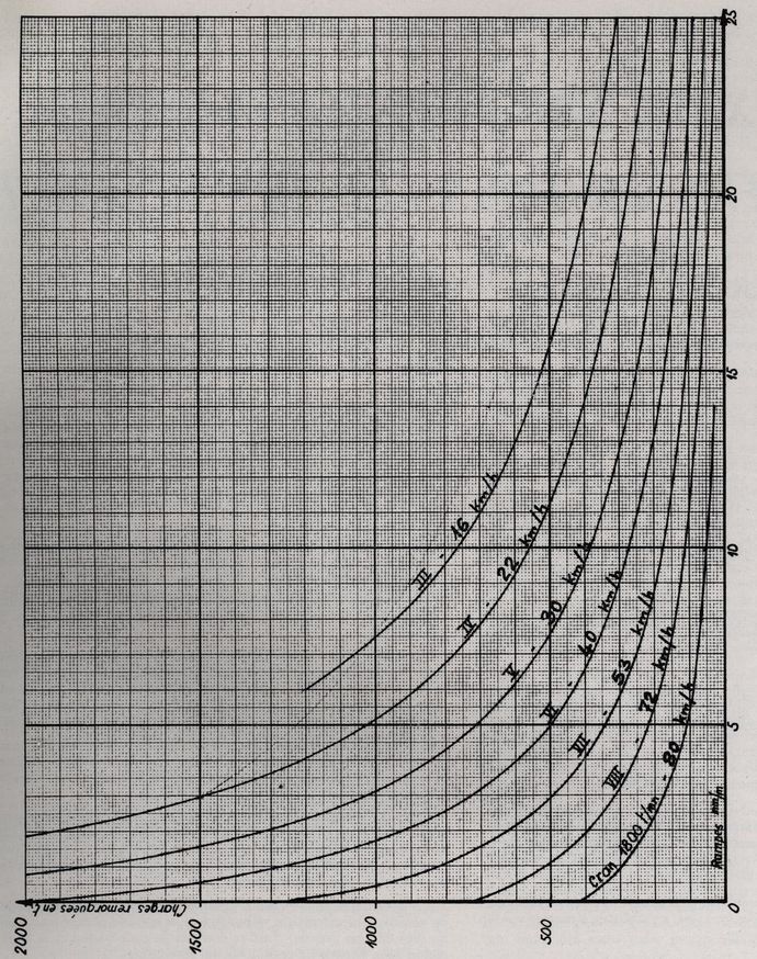
The attached curves are the result.

Photo insertion of curves

Table 1 shows the maximum towable loads in tonnes of freight material, taking into account the profile of the lines and the desired operating speed.

Graph n° 1 represents the network of equivalent curves giving the possible towable load variation of the goods material as a function of the profile conditions, and for a constant operating speed (the curves are drawn for the speed of the train corresponding to the nominal engine speed).

(Annex graph 1&2)

Graph n° 2 represents the network of equivalent curves giving the possible towable load variation of passenger equipment under the same conditions as before, taking into account the best rolling capacity of this equipment.

The following remarkable figures can be deduced from these graphs and tables:

? The BB 71 000 locomotives can tow 2,280 tons of freight at 30 km/h in level.

600 tons of freight material or 1,060 tons of passenger material at 60 km/h.

380 tons of freight material or 800 tons of passenger material at 70 km/h.

170 tonnes of freight or 400 tonnes of passenger equipment at 80 km/h.

? with a ramp of 10 millimetres per metre, they can tow 340 tonnes of freight or 380 tonnes of passenger material at 30 km/h.

115 tonnes of freight or 150 tonnes of passenger equipment at 60 km/h.

80 tons of freight material or 120 tons of passenger material at 70 km/h.

On the other hand, a hook effort of 17 tons in first speed allows the starting of very heavy trains, and a very easy disconnection service at the hump.

Finally, a hook effort of 9 tons at 16 km/h. allows efficient throws.

Locomotive BB 71 000. Passenger equipment trailer

Conclusions

Since their commissioning at the Clermont-Ferrand depot, in replacement of more powerful machines, in shunting operations, and on particularly hard lines in this region, it has been noted that they have a remarkable grip and great flexibility of use

Due to the correct use of the engine and the excellent efficiency of the "ASYNCHRO" transmission a very important fuel saving has been recorded so far.

These robustly built machines require virtually no maintenance and therefore do not cause any downtime in their use.

The "ASYNCHRO" hydromechanical transmission has made it possible to harmonise the cost price and performance qualities. The BB 71 000 locomotives are proof of this.

source : THE RAILWAY AND MOTOR TRANSPORT INDUSTRY

Related Articles

The CFD Company

in the face of the second world war

After having faced the First World War, the C.F.D. company was at its peak an...

The CFD Company

CFD lines and track

The composition of the C.F.D.'s patrimony.

At the time of the Company's most prosperous period, around 1930, the total l...

CFD lines and track

The operation of CFDs

The creation and supply of a machine in less than a year

CFD Company's experience as an operator, now a hundred years old, and the dyn...

The operation of CFDs
Contact us