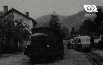
A French mechanical transmission

A French mechanical transmission

The S.N.C.F. uses gearboxes

A locomotive gearbox, designed to avoid an abrupt loss of tractive effort when shifting gears, was used on twin-engine locomotives with a power of up to 800 HP.

Access to our range of gearboxes

From a box two solutions

In 1961, the S.N.C.F. had ordered 35 ZENS gearboxes for diesel locomotives with 150 HP, in addition to the 45 ordered in 1960.

This box was designed by Mr. Pierre ZENS, General Manager of the Cie de Chemins de Fer Départementaux, first of all for diesel locomotives intended for the various lines of the C.F.D. network; and manufactured at the Ateliers C.F.D. de Montmirail where diesel locomotives were built entirely not only for the C.F.D. lines but also for private industry.

Two main ideas guided the development of this box. The first was to obtain a gear change that did not involve a sudden loss of locomotive tractive effort with each passing ; the second was , a gearbox suitable mainly for locomotives rather than railcars , and which could later be adopted for quite considerable power.

Solving the problem led to the gearbox model called "ASYNCHRO"; the second condition having been satisfied by the construction of locomotives of 800 effective HP suitable for both line service and the most arduous operation, although, as a particular consequence of the S.N.C.F. control, of the 80 gearboxes, most of the many transmissions in service are used at less than 400 HP.

Probably more than any other gearbox, the ASYNCHRO gearbox has been specially designed as part of a complete locomotive, and designed by the same technicians.

Originally, small 2- and 5-axle locomotives were built, but the C.F.D.'s activity was directed towards the construction of larger locomotives for traction on several of their lines, and the later development of the locomotive and transmission was considered to be a single issue.

It appeared necessary to avoid any major break in the tractive effort during the change of gearing in order to eliminate shocks and jolts due to the non-rigid coupling of wagons; also to ensure essential continuous traction for the locomotives of 25 to 30 tonnes and over and 300 to 400 HP of effective power that were envisaged.

In addition, with a mechanical transmission, the engine speed is proportional to the driving speed in each gear ratio, and consideration had to be given to being able to disconnect the engine from the driving wheels, for example when shifting gears or during a somewhat rough crash, which was achieved by introducing a freewheeling system between the gearbox and the drive axle, a device which also has other advantages such as preventing overloading of the engine. Finally, a spring-controlled cage model was adopted in preference to the more traditional roller type; and a hydraulic coupler was also inserted in the transmission to obtain a soft start and eliminate clutch wear.

Description of a locomotive transmission.

From the very beginning of its studies of diesel equipment, the C.F.D. envisaged the construction of locomotives more powerful than the first 4 and 6-wheel locomotives, and in fact up to the maximum power required on the six networks.

It was decided that the multi-engine solution would be more satisfactory since the increase in locomotive performance would simply be achieved by multiplying the same engines and transmissions instead of replacing them with different and stronger models. This would remedy the total downtime on the line in the event of a breakdown and, moreover, for small units at least, would allow the use of standard road vehicle engines.

As the power increased, the wheelbase of the two-motor, two-axle locomotives became too large, and a two-truck design was studied which had the merit of lending itself to an almost unlimited increase in power. BB units with 800 effective horsepower were built. On such locomotives all reactions in the couplings are avoided by the fact that the change of the same speed is shifted from one gearbox to the other, so that the locomotive always exerts an appreciable tractive effort.

In the study of this box, the greatest simplicity of manufacture and maintenance was sought. The first step was therefore to eliminate conventional synchronising devices such as cone or multi-plate clutches for each gear stage; with the proviso, however, that whatever the type of transmission, a freewheel device to separate the axles from the transmission was introduced. No difficulty in this respect arose, as there are free wheels with a satisfactory performance with a torque of 600 m.kg.

To meet these requirements, Mr. ZENS adopted an original solution.

It attached a hydraulic coupler to the engine flywheel, and mounted a single main clutch to the input shaft of the gearbox, but located outside the gearbox. Then between the two, attached to the main clutch, a clutch-brake (or synchronizer-zero), the purpose of which is to quickly stop all rotating parts in the gearbox. To make this stop possible, a freewheel was added to the output shaft of the gearbox. There was then no more problem to switch from one combination to the other, all the moving parts of the gearbox being momentarily at rest when the shift takes place. Because of this principle the box was named "ASYNCHRO".

The result was a box as shown in section of figure 2

The clutch-brake and main clutch are on the input shaft on the outside of the housing at the upper right corner of Figure 2. The brake is of the multi-plate clutch type, and can be selected at will as a "dry" or "wet" type. All gears are straight and can be large due to the space available. The shaft brake-main clutch combination is pneumatically controlled by a single cylinder-piston assembly outside the gearbox, and offers two positions :

  • clutch brake
  • (1) engaged and disengaged
  • (2) disengaged tight

As the parts are at rest when shifting gears, it is on parts at rest that the jaws act for each pair of idle sprockets. Attached to the body of the gearbox is a main distributor that directs the impulse compressed air to shift cylinders outside the gearbox; one of these cylinders is shown on the left side of figure 2. The pistons of these cylinders push the splined shafts supporting the jaws and each of these shafts has a cylinder at each end. There are six of these cylinders for an 8-speed gearbox. The valve is controlled from the cab instrument panel through a valve and three groups of lines : A, B and C. Taking into account whether each of them admits air or exhausts it, they can be designated A1 B1 and C1 respectively. A2 B2 and C2. For the 8 speeds the valve combines these lines as follows:

  • 1{suli}th{/suli}speed: A1 B1 C1 5{suli}th{/suli}speed: A2 B1 C1
  • 2{suli}th{/suli} speed : A1 B1 C2 6{suli}th{/suli} speed : A2 B1 C2
  • 3{suli}th{/suli} speed : A1 B2 C1 7{suli}th{/suli} speed : A2 B2 C1
  • 4{suli}th{/suli} speed: A1 B2 C2 8{suli}th{/suli} speed: A2 B2 C2

The driver has a small preselection lever and, nearby, a push button for the impulse. He moves the author selector lever by a small sector to the mark corresponding to the floor he has chosen, and presses the button when he actually wants to shift gear, the operation then being done automatically. After action of the preselection lever and the button, the impulse first moves the piston of a primary valve to the right, then by the effect of the intake air operates the clutch-brake, idles the engine and turns the solenoid valve on the air intake side. Through the second line from the primary valve, the air pressure that held the previously engaged gear control rod is released, and the spring attached to the rod returns it to position for the next movement.

A succession of operations

As soon as the rotating parts have been stopped by the shaft brake (an operation that takes one to one and a half seconds after the push button is pressed), the oil pressure in the gearbox drops to zero a contact closes a circuit to a solenoid valve, which opens the air intake to the main distributor that distributes the necessary air to the control cylinders at the ends of the jaw rods, once the speed stage has been preselected. On the way the air passes through a pressure reducer which can be set to a specific setting. As soon as the crab is in place, the primary valve piston returns to the left, releasing the brake, engaging the clutch, and restoring power to the engine at the initial speed.

In a gearbox where the input shaft is at rest, the input of the gear shift crab is facilitated by an angular movement of the output shaft, which is given by the freewheel when the vehicle is in motion. The shape of the input face of the clutch is also chosen to facilitate its introduction. Although there are two gearboxes on the locomotive, they are both controlled by a single selection movement and a single action of the push button; the only condition is that the control air circuit regulator of one gearbox is slower than that of the other gearbox; thus both gearboxes shift gears with a slight offset and the tractive effort is constantly exerted.

Tractive effort and speed

An important defect of all mechanical transmissions is that the traction speed is proportional to the engine speed for a given speed stage, so that maximum power can only be obtained at the maximum speed in each speed stage. In addition, in the vast majority of mechanical transmissions there is a momentary drop to zero traction effort at each gear shift. The consequences of these two facts are improved in the ZENS ASYNCHRO device as shown in Figure 4. As can be seen, an 8-speed gearbox does not exhibit too large discontinuities in its power-speed curve, and since the two gearboxes of a locomotive change speed at slightly staggered times there is no noticeable drop in locomotive power at those times. Figure 4 also gives Mr. ZENS' own comparison of an 8-speed gearbox and an electric or hydraulic transmission for the same job. Figure 5 shows the tractive effort curve of the locomotive shown in Figure 6. With an all-purpose locomotive with a maximum speed of 80 to 85 km/h, an 8-speed gearbox gives a good spread, with relatively few differences in tractive effort and speed for each stage.

source : Excerpt from DIESEL RAILWAY TRACTION September 1961 P.333 and Seq.

Related Articles

Hydro-mechanical transmissions

for railcars and high-power diesel locomotives

Manufacturers of high-power diesel locomotives generally use either electric ...

Contact us