Transmissions for diesel locomotives and the origin of the first ideas of "ASYNCHRO"

By Mr. ZENS and Mr. HONNORÉ Managing Director and Director of the Chemins de Fer Départementeaux.

The note below, which naturally expresses the personal opinions of the authors, is intended to develop the general ideas, theories and results of experience which justify the use of mechanical transmissions on diesel-powered engines, even of high power, subject to certain appropriate provisions.

Access to our range of gearboxes

The different transmissions for diesel locomotives

It is currently a common opinion that transmissions for diesel locomotives can be classified as follows:

  • mechanical transmissions for low power,
  • hydraulic transmissions for medium power,
  • electrical transmissions for high power.

It may seem daring to attempt to change such a generally accepted opinion.

We must therefore say right now that our opinion on this issue is backed up by several years not only of tests but of services; and it is likely that if the results obtained are not yet sufficiently known, it is because these services have been carried out on a scale that is insufficient to be advertised.

Many technicians will not be extremely surprised since theory shows that mechanical transmissions have by far the best performance and that not everything has yet been tried to adapt them to "diesel" traction and eliminate their major defects which are: the difficulty of transmitting high power, the lack of flexibility at start-up and the difficulty of obtaining continuity of traction effort.

We readily admit that the starting flexibility of a mechanical transmission cannot be achieved by means of friction materials. As things stand at present, the most suitable component is the hydraulic coupling, which has an excellent performance in normal use.

The use of several engines

The simplest way to ensure continuity of the tractive effort is to use at least 2 motors in such a way that the effort of one of them can be interrupted without damage for a relatively short period of time to allow the gear ratio of its transmission to be changed. These engines can run momentarily at speeds in the gear ratio of the gearbox reason which is perfectly admissible, even for a very long time.

We will see further on that having several engines is only an apparent complication, as it is far from being a cost overload, and is even a very important element of operating economy .

We believe, on the other hand, that with a single mechanical transmission, continuous traction is only possible with a considerable and unquantifiable increase in the instantaneous forces imposed on the transmission.

This is because, assuming that the convoy speed remains constant during the combination change, the engine speed must during this time vary as the reason for the gearbox and this can only be done instantaneously at the cost of an instantaneous overload of the transmission and the clutch in particular.

Simple but effective gearboxes

The various gearbox combinations

With regard to the gearbox itself, gearboxes must be made as simple as possible. To date, many combinations have been tried out and we will not allow ourselves to criticise them here. They are either with multiple clutches, with satellites with multiple brakes, or with synchronized gears. Thanks to the high precision of machining and careful, but often delicate adjustments, certain results have been achieved. However, to date, these have not appeared to be of such a nature as to allow them to outweigh hydraulic or electric transmissions, despite the disadvantages of the latter in terms of efficiency and price.

On the other hand, it seems likely that if the qualities required of the transmissions could be obtained by using gearboxes with only parallel shafts carrying simple, generously dimensioned spur gears and fitted with ordinary gear claws, the mechanics would be robust and simple enough to ensure low cost, high efficiency and increased longevity.

The elimination of the synchronizer

To build it so simply it is therefore necessary to be able to eliminate an organ which is nevertheless very much appreciated: the synchronizer.

A synchronizer is a brake that is difficult to interpose between the gears, as it must absorb the differences in the dynamic forces when shifting gears.

The calculation shows that due to the small space available it is a very loaded brake. Its location makes it impossible to maintain it and, above all, its extrapolation has limits that are quickly reached for rail power.

Calculation of the synchronizer

If a gearbox B. V.1 synchronized gearbox can transmit a power and we look for the similarity ratio to build a similar gearbox B..K transmitting a power PK equal to KP1 it is sufficient to apply to all gears an expansion in the ratio or K1/3

Indeed either any pinion of module M1 of width L1 and having n teeth, the transmissible torque is proportional to: nxL1x M21 M

If we keep the same number of teeth and if we modify this pinion by expanding it cubically according to the ratio K1/3, the new transmissible torque will be proportional to : n K1/3 L1M21 K2/ 3 = K n L1 M21= nLK M2

As we do not change the angular velocities, such a gearbox will pass a power PK = K P1

Let's see what happens to the synchronizers.

A synchronizer essentially absorbs a variation of kinetic energy, so it is a work proportional to I??2 (??2 being the variation of the square of the angular velocity of the masses to be tuned ? I representing a moment of inertia). This work will vary as I, i.e. as the fifth power of a length.

If then T1 represents the work absorbed when passing any gear of the B gearbox. V..1 for the gearbox B.V.K under the same conditions the corresponding synchronizer will have to absorb a job TK =K5/3T1

Let's go back to the B.V.K, where all the components have been expanded in the ratio K1/3, and see the T'K work of such a synchronizer. T'T'T'K is proportional to C'K ??, ?? being the same in both cases.

The work T'K varies as the torque of the synchronizer.

This torque is equal to : C'C'C'K = p x SK xrmK xf

where..

  • p = unit pressure
  • SK = friction area
  • rmK = average radius
  • f = coefficient of friction
  • so if we keep
  • same unit pressure: p Sp S= K2/3 .S 1
  • same coefficient: f rmf rmK = K1/3rm1
  • C'C'K K3/3C1

hence

T' k = K3/3 T1; where the requested ratio is TK /1 = K5/3

To restore the balance we would have to increase the synchronizers by expanding them in the ratio ?(K5/3) that is K5/9, instead of K1/3 for the rest of the box.

Asynchro: the solution to problems

We can see that very quickly the "synchronizer" exceeds the dimension of the pinion to be synchronized .

In fact, there are hardly any synchronised gearboxes in the world that give full satisfaction for power ratings above 300 hp.

On the other hand, it can be stated that any mechanical locomotive transmission must - as a matter of absolute safety - be equipped with a freewheel to protect the engine from reactions or overspeeds due to the train. There can be no question of an "engine" brake when there is in many cases less than one horsepower per towed ton.

It can also be said - this point having been controversial several years ago - that there are today several freewheel systems that give full satisfaction even for torques of the order of 600 m/kg.

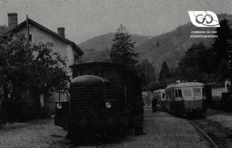
Fig. 1 - "Continuous traction" hydro-mechanical diesel locomotive, equipped with 2 power units and "Asynchro" gearboxes

Under these conditions, the following provision was made:

The coupling being fixed on the engine flywheel and the clutch on the primary of the gearbox, one interposes between this clutch and the gearbox, a brake which one could call a "zero synchronizer" since it is intended to quickly stop all the gearbox components. This operation being made possible, a free wheel being located at the outlet of the gearbox , there is therefore no more gear shifting problem, all the gearbox components being at rest.

This is the principle upon which the Asynchro box was built

source : Revue Générale des Chemins de Fer, June 1957

Related Articles

Hydro-mechanical transmissions

for railcars and high-power diesel locomotives

Manufacturers of high-power diesel locomotives generally use either electric ...

Contact us