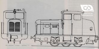
The pneumatic controls of the 400 CH 34 T tractor

The pneumatic controls of the 400 CH 34 T tractor

The special feature of the pneumatic control of the 400 CH 34 t tractor is that the gear changes are not made simultaneously on both gearboxes, but successively, so that the tractive effort during the gear changes is never broken, which makes the traction continuous.

Access to our range of shunters

The realization of the controls

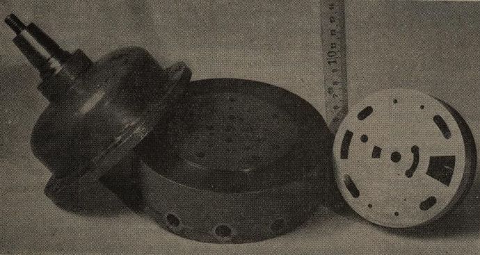
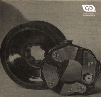
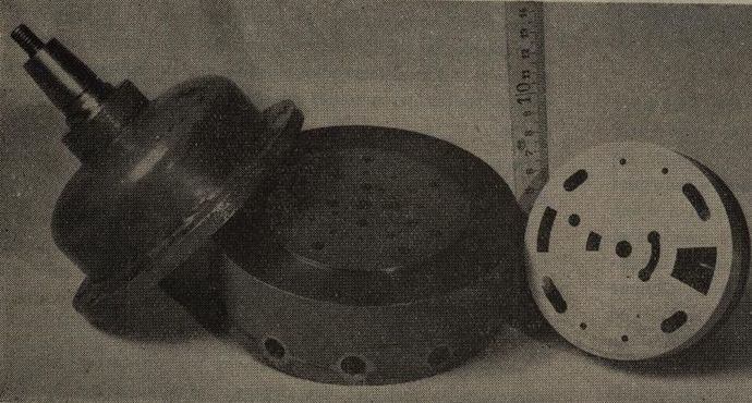
The controls are automatically carried out by means of simple devices, thus pneumatic control of the gearboxes is obtained by a spool valve with a rotary slide similar to that of a brake valve (Fig. 9).

Fig. 9 - Distributor.

This device carries out all the operations of changing the eleven gears in one turn, in the desired order, and requires no more maintenance than a mechanic's valve.

The pneumatic control cylinders that act on the rods controlling the speed ranges are mass-produced cylinders for truck brake equipment: they are inexpensive and easy to repair or replace.

Moreover, they are perfectly tuned, since they are safety devices on the road.

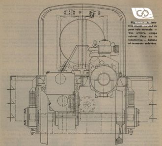
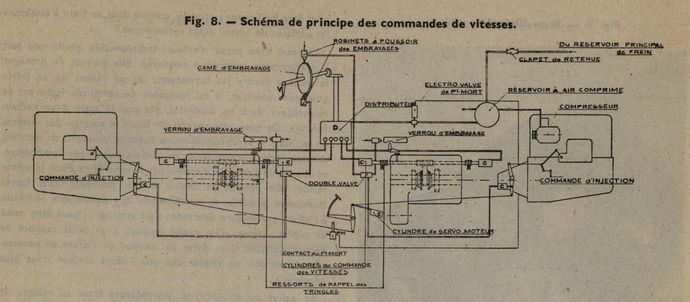
The diagram shows all the tractor controls as carried out by this valve.

Fig. 8 - Schematic diagram of speed controls.

Driving

The locomotive engineer has at his disposal (Fig. 10), in addition to the brake valve :

  • 1° A hand throttle control by which it can regulate the flow rate of the injection pumps, therefore the torque of the engines, this torque being identical for both engines.
  • 2° For starting, a disengagement pedal is used to operate the two clutches simultaneously and effortlessly by means of a pneumatic servo-motor. This pedal, at full travel, actuates by a toggle contact a neutral solenoid valve, as we will see later.
  • 3° A gear shift handwheel. This steering wheel makes it possible to select one of the eleven speed combinations:
  • Box No. 1... 1 1 2 2 3 3 4 4 5 5 6
  • Gearbox No. 2... 1 2 2 3 3 4 4 5 5 6 6
Fig. 10 - Control station.

Distributors

These combinations are obtained by means of the valve, which admits the compressed air successively into the cylinders of the speed controls corresponding to these different combinations, each cylinder not supplied being exhausted and the corresponding speed returning to neutral, by means of a spring R arranged in a cage designed for this purpose.

The valve therefore has eleven positions, which are obtained by rotating the valve by 30° between each position. Each 30° rotation results from half a turn of the handwheel V which drives the valve shaft by means of a worm gearbox with the ratio 1/6.

Each valve position is obtained when the handwheel crank is on the same vertical selected diameter. When the handwheel is in the down position, the gears engaged are identical on both gearboxes (1?1, 2=2, 3=3, etc.). When the crank is in the up position, the speeds selected are different (1=2, 2=3, 3=4, etc.).

A clutch cam is placed on the shaft of the handwheel, and disengages successively, and in the desired order, the engine unit on which the gear ratio is to be changed. A clutch lock prevents re-engagement until the gear rods are in the correct position.

The driver facing the controls

The driver does not have to manoeuvre the throttle control between each gear change, because a very simple mechanical device cuts off the injection of the engine, whose speed will be changed before disengagement, and gradually returns the injection to its original position during re-engagement.

Neutral can be achieved at any time by fully depressing the clutch pedal. An electrical contact (P.M.) is reversed each time the clutch pedal is fully depressed. It turns on or off a solenoid valve (E.V.) in the compressed air supply circuit to the distributor.

For example, when the locomotive is stationary and the driver wants to start, he places the hand wheel in the 1re_1 position, disengages the clutch fully, places the throttle lever in the start position and slowly raises the clutch pedal. He can then adjust the throttle lever, taking into account the train load and the desired starting speed. As soon as he has reached a reasonable speed, he only has to turn the hand wheel half a turn, then another half turn and so on until the locomotive reaches maximum speed.

Thanks to the presence of the freewheel, no wrong operation can be made . Thus, without any inconvenience, and at full speed, it is possible to place the handwheel on all lower gears.

If, by mistake, the mechanic clutches at a speed too high for the speed of the tractor, the only disadvantage is to stall the engine; but this always happens, thanks to the device described above, when the engine is at low revs, so neither the engine nor the clutch has to suffer.

In the event of an emergency stop, the clutch pedal is pressed down fully This will bring the engines to idle, the clutches disengaged and the gearboxes returned to neutral.

It is also possible, without any inconvenience, to change from one gear to another without having to go through the intermediate gears, which simplifies driving when, in the middle of the track, the train has had to slow down.

The shuttle controls on each deck are operated by compressed air using the same compressed air cylinders as those acting on the gear rods, the shuttle lever acts on Westinghouse push taps.

It should be noted that with this device you can, for example, drive in 3rd gear on one motor and in 4th gear on the other for as long as you want. Their speeds will be different, you just have to watch that they stay within the usual limits.

On the other hand, it should be noted that this arrangement gives 11 speeds and that in some ramps a load is towed better in 4/5 than in 4/4 or 5/5.
source : Excerpt from the Revue Générale des Chemins de Fer N° of September 1950

Related Articles

The first tests

the Thomson-Houston tractor from the C.F.D.

As early as 1920, after the events of the 1914-1918 war, the secondary lines ...

The first tests

The First Tests

the C.F.D.'s Petolat tractor.

In order to carry out the numerous maneuvers at Gueugnon station on their SaÃ...

The First Tests

Series tractors

type Indre-et-Loire (Series 11 to 16)

After the construction of tractor No. 4, the C.F.D. determined the definitive...

Series tractors

Series tractors

charentes type (Series 50-62-70-201)

Following the directives of the Central Administration, Mr. Esbelin, who had ...

Series tractors
Contact us