The transmission of the tractor 400 CH 34 T

The transmission of the tractor 400 CH 34 T

Mechanical transmission

The financial and technical advantages brought by the mechanical transmission, pushed the Departmental Railway Company to adopt this type of transmission to complete the construction of the 400 dh 34 t tractor.

Access to our range of shunters

The composition of the transmission

The transmission is composed of: a Comete Mecano La. 120 tri-disc clutch, or alternatively 14 L.F. bi-disc

These classic clutches are easy to maintain. They are integral with the engine and are connected to the gearbox by means of a Glaenzer-Spicer type 1700 cardan shaft.

The advantage of this arrangement is that no precision is required in the motor-gearbox alignment and, therefore, the assembly and disassembly of these components is made easier.

A gearbox specially built by Société des Procédés Minerva provides six different gears For this purpose, it has a mechanism giving three gears that can be doubled by means of a double gear ratio device.

These six speeds follow one another in an approximately geometrical progression.

The following gear ratios are obtained for I 500 rpm at the motor:

  • 1{suli}re{/suli} speed 8.8 4th speed 26
  • 2nd gear 13 5° speed 38
  • 3rd speed 18.6 6th speed 54.5

The gears belonging either to the group giving the three speeds or to the doubler, have their teeth always in mesh, their drive is carried out by means of splined shafts mounted on ball or roller bearings. The gears that are not under load, rotating idly around their shaft, are also mounted on bearings. They are fixed to the shaft that supports them by means of high-capacity synchronising claws. The synchronizers are of the so-called "inertia" type, which are very efficient, and only allow the speed to be jawed when the synchronization is completely complete.

The control of the synchronizing crabs is obtained by means of steel forks with bronze inserts.

These forks are attached to rods controlled by means of compressed air cylinders attached to the front and rear of the gearbox.

The gearbox is completed by a compartment containing a set of reduction gears controlling the output shaft, which allows, by only changing the ratio of these gears, to make locomotives with different speeds.

The Freewheel

At the output of the gearbox there is a freewheel, and here an originality should be pointed out: The freewheels of the new design have been tested for a torque of 360 m/kg. They do not have rollers like conventional freewheels, they are "bar" freewheels of a new design. In all designs with wedging elements such as rollers or discs, each of these elements work in parallel with the others. Since, as a result of secondary phenomena (vibrations, etc.) it is not possible to get the rollers to work evenly, which sometimes results in local overloads that cannot be determined, steels with very high hardness and good impact strength must be used, which makes it difficult to produce them.

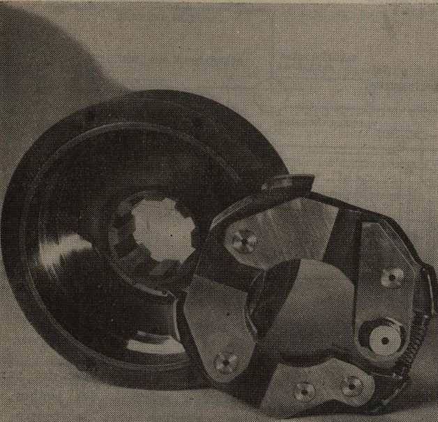
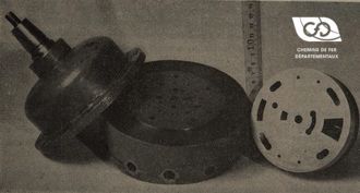
Fig. 5 - Freewheel disassembled.

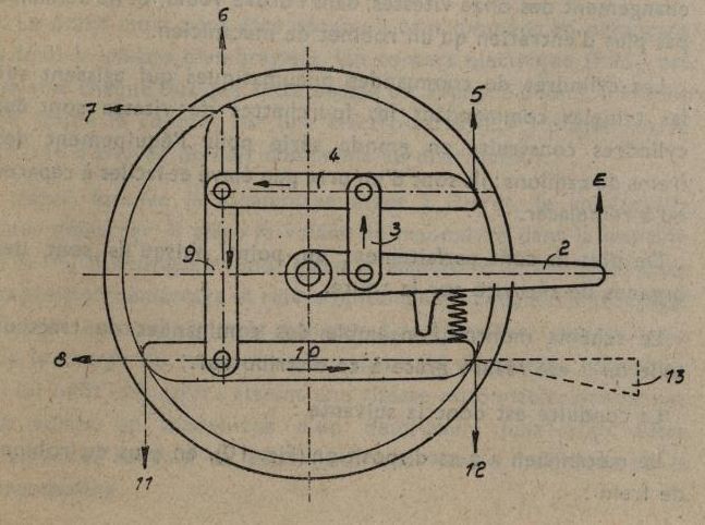
In the bar freewheels (Fig. 5 and 6) (L.R. licence) the contacts between the driving and driven parts are no longer lines but the surface of 4 shoes, so the unit pressures are reduced. They can be calculated for the 4 contact shoes by means of a static mechanics diagram and these 4 points work in series and not in parallel; the effort on each of them is therefore determinable. Finally, the wear can be easily compensated, as in a drum brake, as the working surfaces are cylindrical.

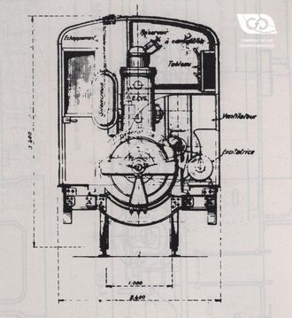
Fig. 6 - Schematic diagram of the freewheel.

The importance of the Freewheel

The freewheel seems to be indispensable whatever the mechanical transmission used. It protects the engine against overspeed , because due to its low power-to-weight ratio, it cannot be used as a brake or retarder on slopes, as soon as the train has a certain tonnage. Moreover, it allows the gear change to be hastened by facilitating synchronisation, as the gearbox is isolated on the engine side by the clutch and on the axle drive side by the freewheel. For the same reason, it allows you to choose at any time, without any possible misuse, the combination that best suits the effort that is going to be required; this is how it can be shifted in full gear, from a high gear to a low gear ratio. It prevents engine wear by allowing the engine to idle as soon as the engine power is no longer required.

On a level or sloping ground, with the engines at idle, the tractor "runs" freely and at a speed which may exceed that provided by its maximum gear ratio. This results in fuel savings and a very appreciable reduction in fatigue, because railroad tracks have, by their very nature, gentler but also longer slopes than those encountered on roads, so freewheeling is a very long process.

The axles

From the freewheel to the axle drive the movement is transmitted by a Glaenzer-Spicer type 1800 PTO shaft.

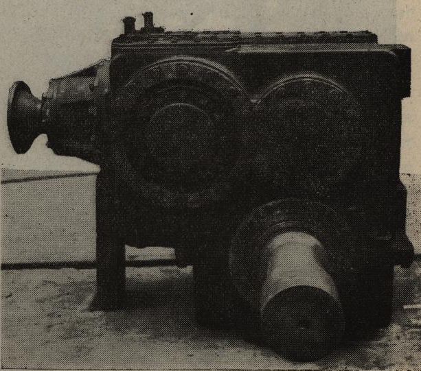
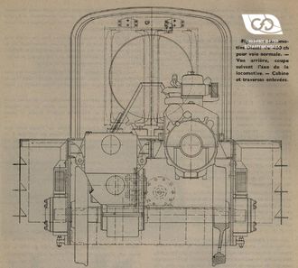
The attack of each of the two axles (Fig. 7) comprises a mechanism for reversing the direction of travel consisting of 3 bevel pinions, a first stage of reduction gears followed by a second reduction stage to which the ring gear integral with the axle also belongs.

Fig. 7 - Engine deck.

The housing, consisting mainly of an upper housing containing the majority of the mechanical parts, is completed by a lower housing. The separation passing through the axle axis allows the axle with its crown gear, bearings, etc... to be fitted and removed. The main housing is subdivided into two separate compartments, separated by a partition through which the shaft of the first gearbox passes.

The overturning torque of the axles is maintained by means of reaction struts oriented towards the centre of the chassis so as to reduce the effects of the wheelie rotations.

It should be noted that the axles are independent, which helps to improve the efficiency of the transmission.

Any coupling (connecting rods, chains, cardan shafts) forcing the driving wheels to turn at the same speed forces the lightest axle to slip slightly at all times, as the tyres are never the same diameter and the wheel set is "flanged" in an appreciable way.

source : Excerpt from the Revue Générale des Chemins de fer N° of September 1950

Related Articles

The first tests

the Thomson-Houston tractor from the C.F.D.

As early as 1920, after the events of the 1914-1918 war, the secondary lines ...

The first tests

The First Tests

the C.F.D.'s Petolat tractor.

In order to carry out the numerous maneuvers at Gueugnon station on their SaÃ...

The First Tests

Series tractors

type Indre-et-Loire (Series 11 to 16)

After the construction of tractor No. 4, the C.F.D. determined the definitive...

Series tractors

Series tractors

charentes type (Series 50-62-70-201)

Following the directives of the Central Administration, Mr. Esbelin, who had ...

Series tractors
Contact us